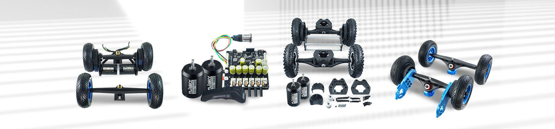


Flipsky FSESC Gateway Interface | Multi‑ESC Network Cooperative Control, UART PPM ADC Input, USB Passthrough for VESC ESCs
Specifications:
- Remote firmware version: 7.0
- Programmable Tool: VESC_TOOL_7.0
- Communication Ports: USB, CAN, UART, PPM, ADC
- Size: L47mm*W36mm*H17.6mm(with aluminum enclosure)
Features:
- Compatible with all FSESC(VESC) types, supporting multi-ESC networked cooperative control.
- Supports UART/ PPM/ ADC control input; the active control mode can be selected via the VESC_TOOL.
- Converts throttle, brake, steering, gear, and other inputs into CAN control commands.
- Control Modes Supported: Current, Duty Cycle, and Speed Control.
- Transmit back voltage, current, rotational speed, temperature, duty cycle, and fault status via UART or USB.
- Retains USB passthrough functionality, allowing the upper computer to directly access, identify, and
configu re the specific ESC via CAN ID.
Wiring diagram:


Cautions:
- The module requires a 5V power supply only. Direct connection to the battery bus or exceeding
the hardware's rated voltage is strictly prohibited.
- Keep CAN cables away from motor phase wires and high-current conductors. It is recommended
to use twisted-pair cables and minimize stub lengths.
- The CAN ID of multiple FSESCs must be unique; in case of ID conflict, manually modify the ID
by connecting the ESC via USB.
- Set the FSESC gateway control mode via the VESC_Tool, and verify that the CAN baud rate
is uniform for all FSESCs.
- Status LED Indicators: The blue and green LEDs are always on when working; the green LED lights
brightly during the drive state; the red LED flashes in upgrade mode; the red LED light stays on
continuously during ESC fault.
- Default control mode: UART. Manual configuration via upper computer or Bluetooth connection required.
Manual:
https://cdn.shopify.com/s/files/1/0011/4039/1996/files/FSESC_-_V7.0_20261026_1.pdf?v=1793691314