Spec:
- Hardware: V2.2
- Max voltage: 12S (50.4V)
- Continuous Current: 60A , Max Current: 120A
- Burst current: 800A(theoretical current)
- Mosfets: NVMFS5C628NLs
- LED button diameter:12mm, cable length: 250mm
- PCB thickness:4 layers*3oz copper=12oz copper
- PCB size: 40mm*32m
- Wire:12AWG
Enhanced Features:
- High Side Switching -> Much safer to use with multiple ESCs and other devices.
- In-rush current limiting.
- RC delay network restricts inrush current to safe levels.
- dV/dt is ~100V/s (This is considered VERY slow for power electronics. Fast would be 50,000,000V/s). At 6,000 uF output capacitance, this is an inrush current of 600mA.
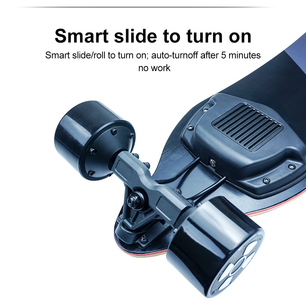
- Smart Power on/off
- Roll-to-start. Has 12 second blanking timer after turn off. Can still be turned on by switch during this period.
- Auto-turn-off. Will turn off automatically after 20 minutes. The output voltage must vary by at least 500mV within any three second interval to reset the turn-off timer.
- Support momentary push button. Hold for 0.3s to turn on, 1s to turn off. Holding it down will cycle it on then off.
- High power, 150A Continuous.
- Very low idle power draw, ~300uA, will last months on battery.

1.Preventing a small spark may cause explosions in some spark-sensitive areas.
2. Add copper bars for better heat dissipation and over-current flow.
3.Anodized aluminum Heatsink with lots of notches for better heat dissipation.
4.Add silicon glue to fix the LED button cable with the heat shrink.
Warnings:
- Do not peel off the heat shrink.There’s no screw to lock the heatsink and PCBA. Only the heat-transfer silicon pad is naturally sticky to heatsink and PCBA.
- No short circuit protection, DO NOT short circuit output!
- No reverse polarity protection. DO NOT plug in backwards.
- Recommended to keep output capacitance under 6,000 uF. Proper operation cannot be guaranteed at higher capacitances.
- Do not Hot-Swap. Try to make sure everything is off before connecting and removing. If need be, unplug from battery first, wait for ESCs to turn off, then unplug ESCs. Do the reverse for plugging in, plug in ESCs first before plugging the switch into the battery.
- Engineers have thoroughly tested prototypes; however, this is still a new design and a first production run, please exercise extreme caution (as one would normally do with any electric vehicle) when using this device.
- Do not attempt to reprogram the MCU unless otherwise advised. Doing so will void any warranty and also put the switch at great risk of failure.
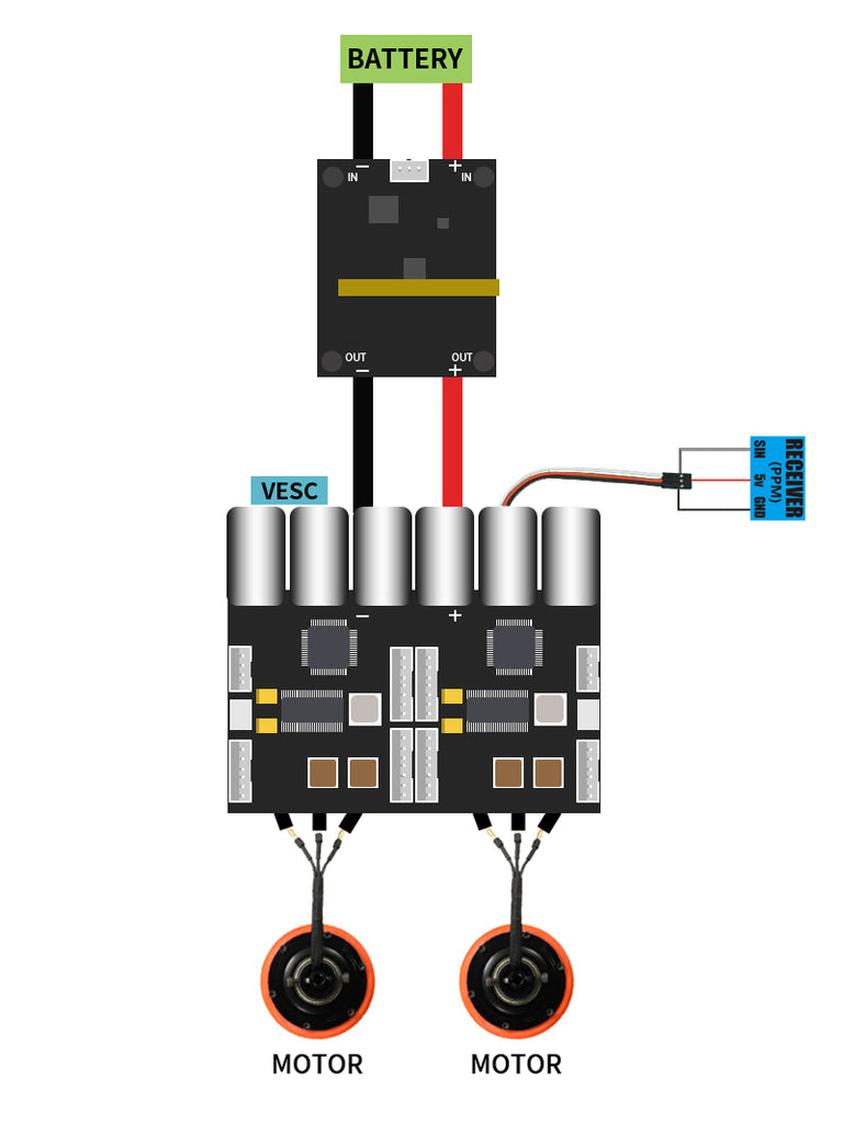
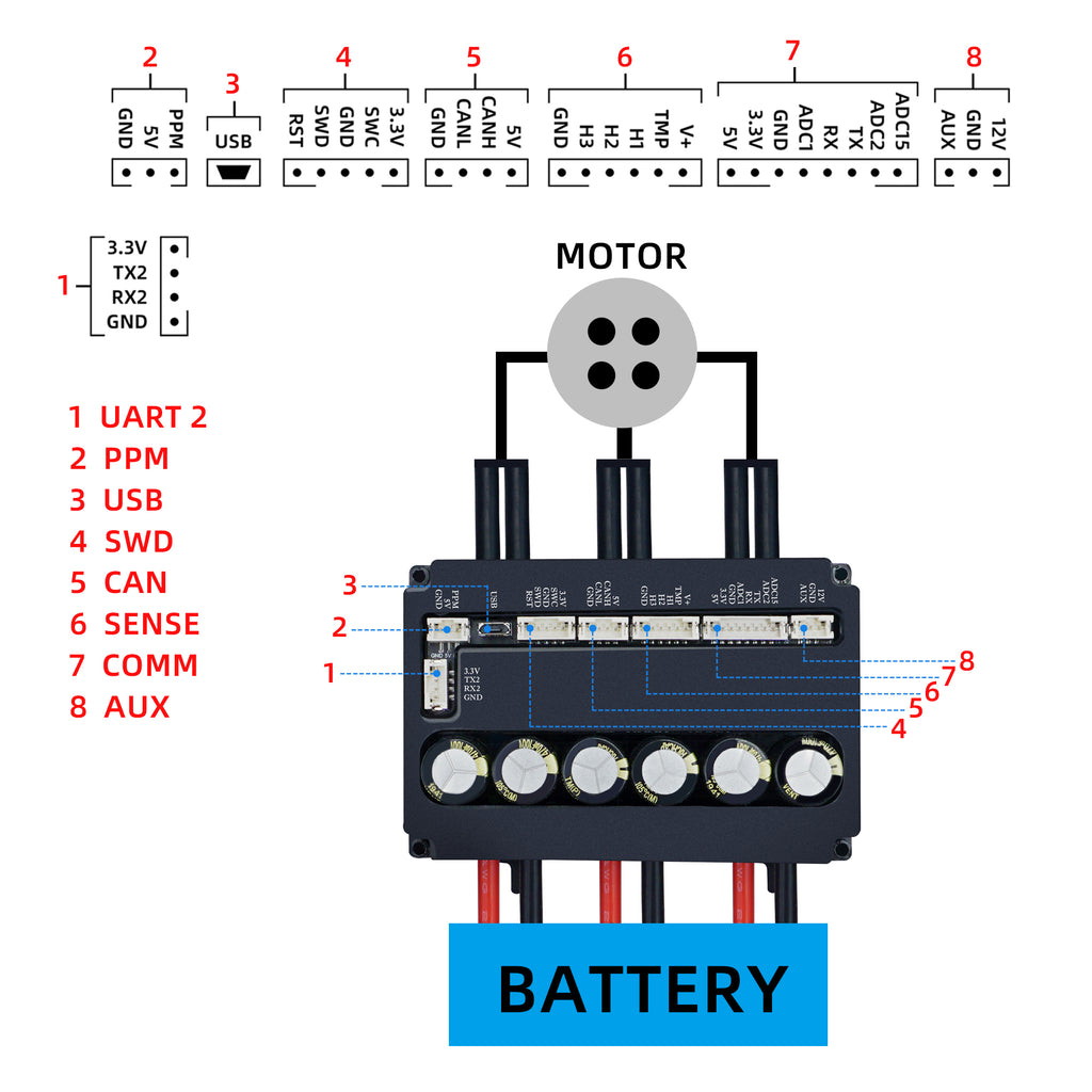
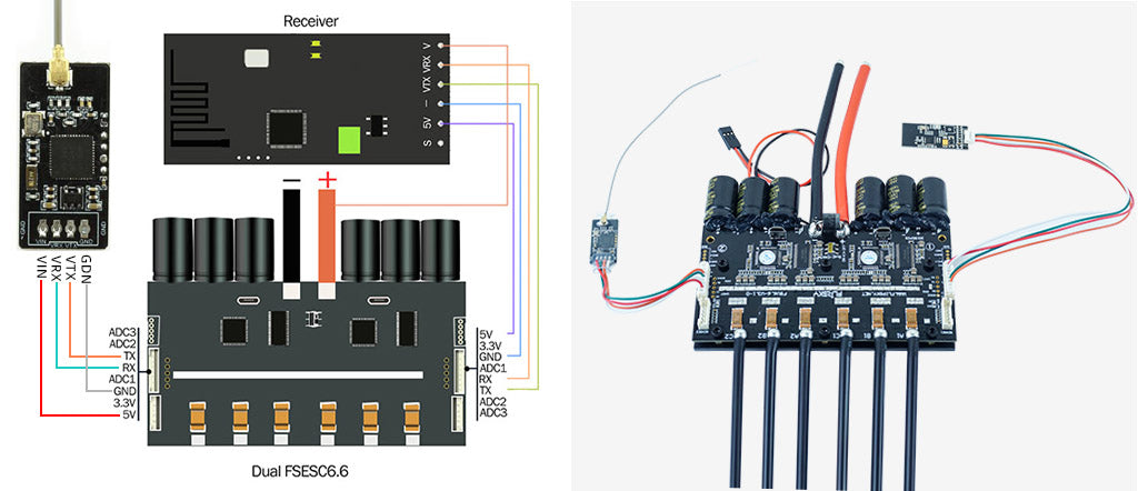
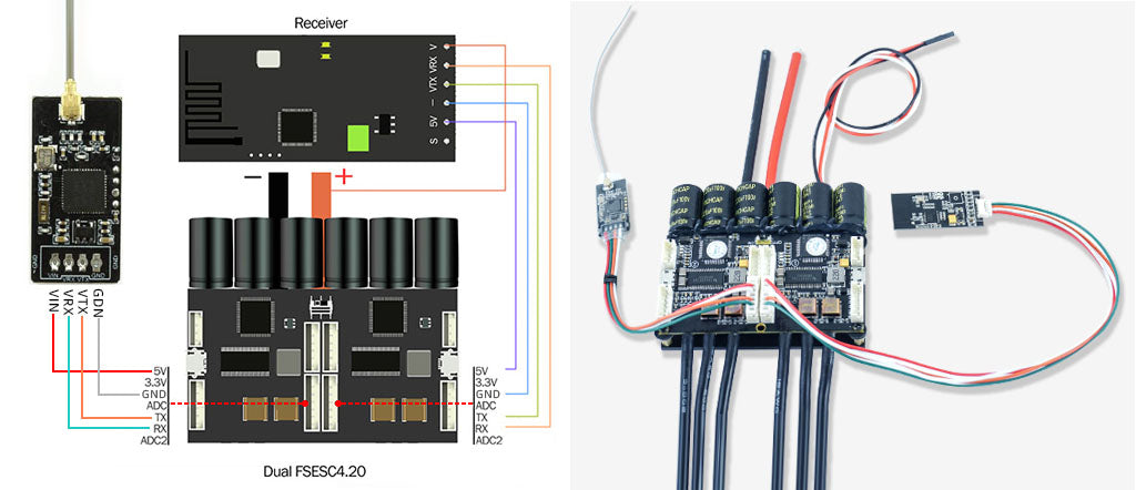
Wiring diagram: